Zuki Audio Eleets 4-Channel Amplifier
Disclaimer: This review is strictly "my opinion", and should be taken as such. Any information provided should be considered yourself, as I am not a "professional reviewer", nor am I an "expert" on amplifier design. Also, I am not paid or compensated in any way (other than getting to play with the product in question for a short period of time) by the manufacturer of this product, so don't expect any portion of my review to be "sugar coated"
First off, I would like to thank members of the Phoenix Phorum (www.phoenixphorum.com) and DIY Mobile Audio forum (www.diymobileaudio.com) for pooling their money and sending me this amp to test. These amps have caused quite a stir at different online forums, and the time had come to put one through its paces to see what all the hype is about, or if the product had any value to offer.
Like any other review I have done, I try to keep things as objective as I can, but it is impossible for me to not personally form an opinion on many aspects of a piece of equipment. I do my best to simply provide information, and leave it up to you the reader to form your own opinions.
Cosmetics:
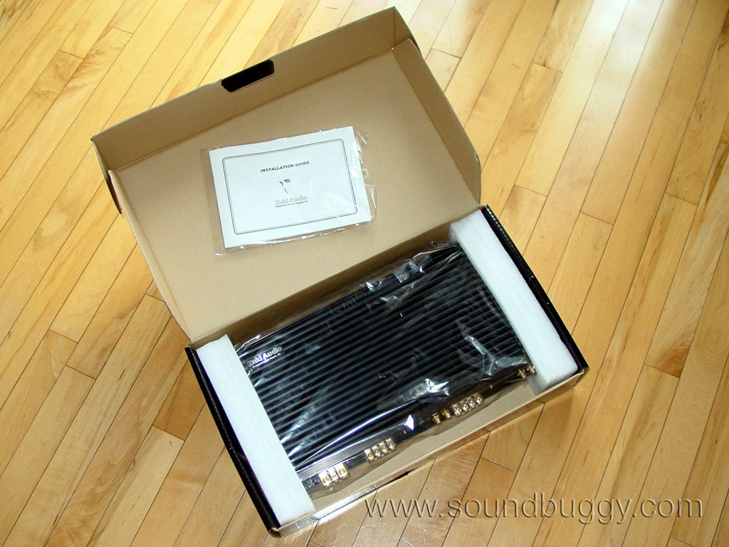
The amp arrived well packaged and with a few bonuses thrown in the box. There were 14 demo CDs, a copy of the local newspaper, and a LED keychain. Apparently Zuki is concerned for my safety at night when I am fumbling for my keys to the front door, or if I happen to find myself alone in a dark alley.
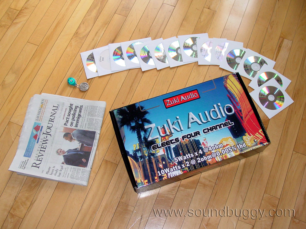
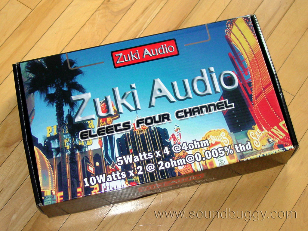
The box is colorful and opens and closes well, plus it is evident it does a good job keeping the amp secure, which in my opinion is the number one concern for the box in the first place.
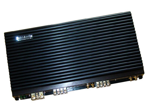
The amp is simple and clean. Really it is exactly what I want to see in an amp. It won't give you that feeling you have an alien spacecraft in your trunk, or you are trying to simulate the Pink Floyd laser light show either.
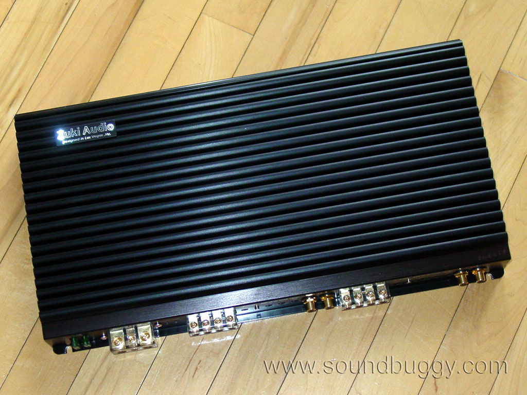
Later on when I got around to powering it up, I found the blue power LED to be a bit bright. I think it would double as a trunk light it is that bright. I guess you can't have everything, and it is probably better it is too bright than too dim.
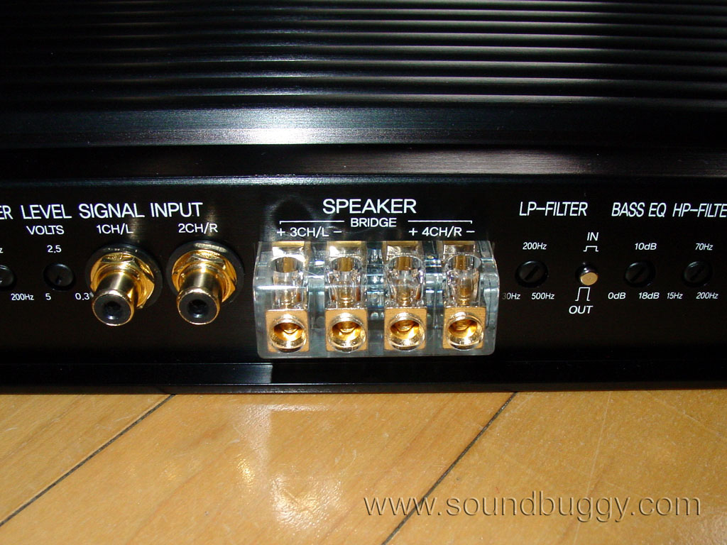
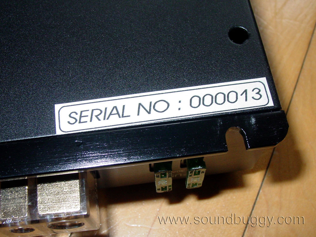
I am not a fan of the terminals. They are nice in that they use standard Phillips screws, not Allen screws, but I don't like the clear plastic. It just reminds me too much of junk flea market amps like Audiobahn. Now here is a strange find, dual 30A fuses. If this amp is only 5W like it is rated, I hardly see the need for dual 30A fuses.
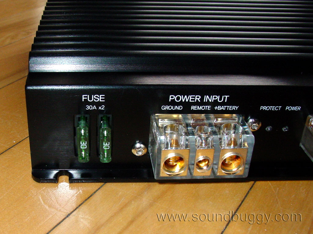
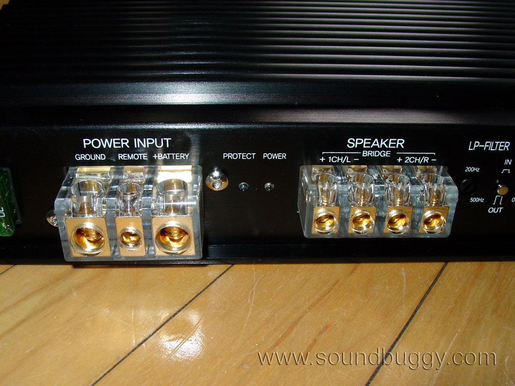
Notice the protection and power lights? I think some online discussion about this amp has been its lack of protection, well why would it have a protect light if it is never going to make use of it?
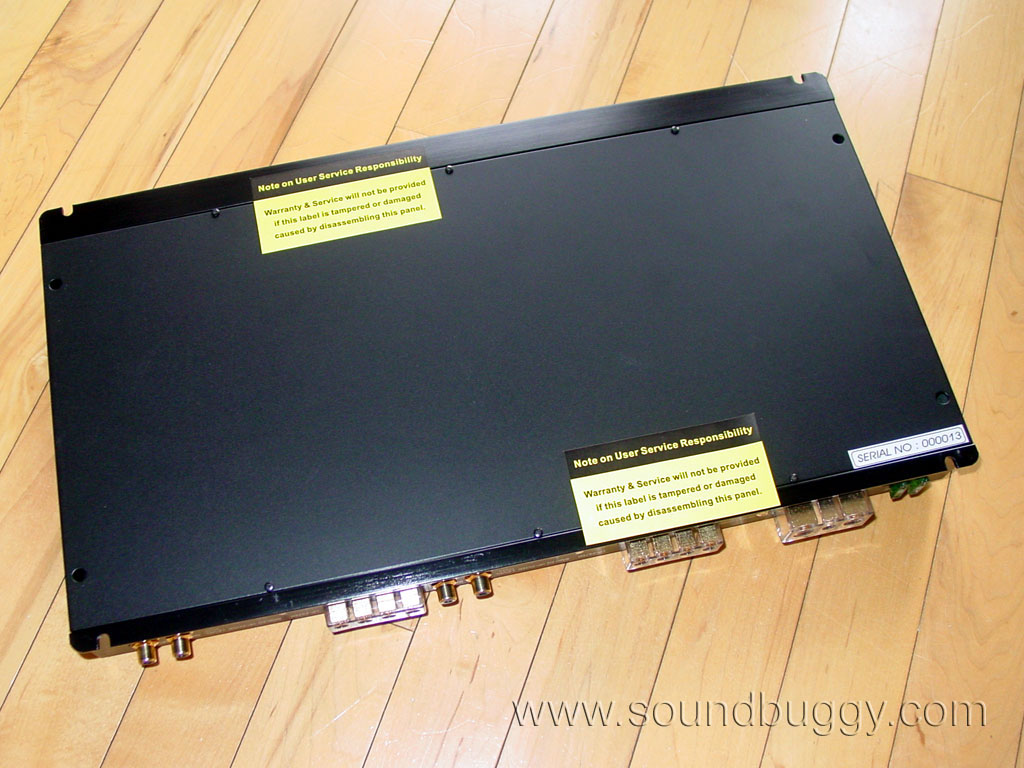

The amp has seals on the bottom to prevent tampering (we'll see about that), and a sticker with the serial number 13. If this is only amp 13, I sure hope all the bugs have been worked out of these.
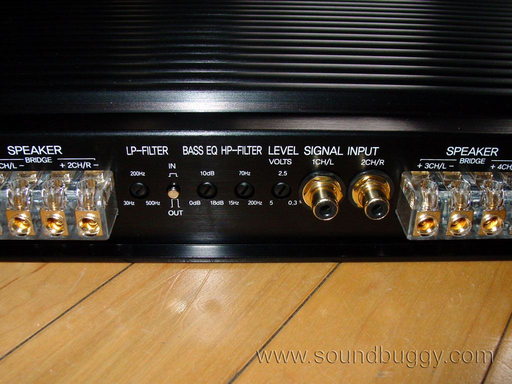
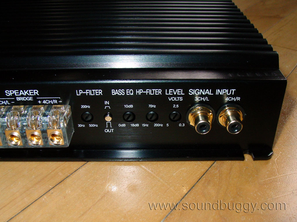
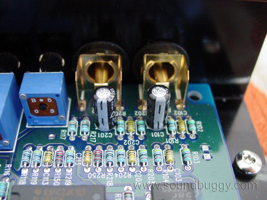
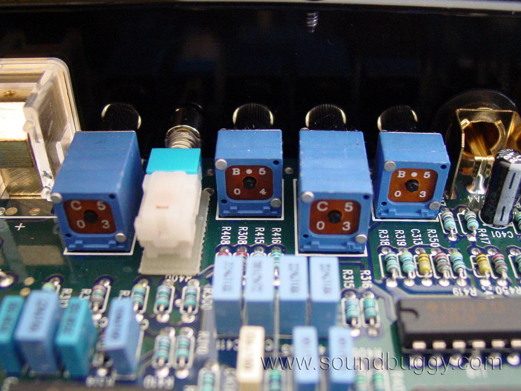
I was a bit bummed to find the amp does not have a defeatable crossover. It is either high pass, or low pass, but cannot be just off. To run the amp full range you have to turn the crossover all the way down to 15Hz. There are also bass boost controls on the amp, but I could care less about bass boost and will leave studying that up to someone else in cyberspace. The RCA jacks are very nice ones which mount solidly to the amp heatsink, and worked very smoothly with my chosen RCA cables.
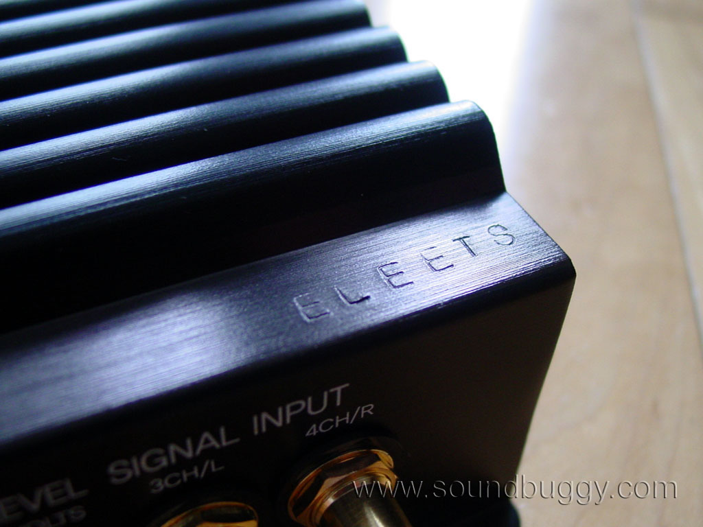
The word "ELEETS" is stamped into the heatsink. My best guess is the guy stamping the word on there was either drunk or blind. Maybe it was intended for the letters to slant off to nowhere, but I would have been far more impressed to see them in a straight line, or better yet, CNC milled in perfectly.
Overall the amp is clean. I mean really clean. It is entirely functional looking, not gimmicky, and for this I give it big bonus points.
Build:
I found a way around the tamper seals on the bottom of the amp and cracked it open to be greeted with this...

Well, it looks like this amp was really built for me.
Online a lot of people have discussed how this amp is a knock off or a copy of other amps. I feel this could not be further from the truth. Yes the amp uses similar features such as the devices being sandwiched between the PCB and the heatsink, but there are countless differences and it all adds up to a pretty unique design.
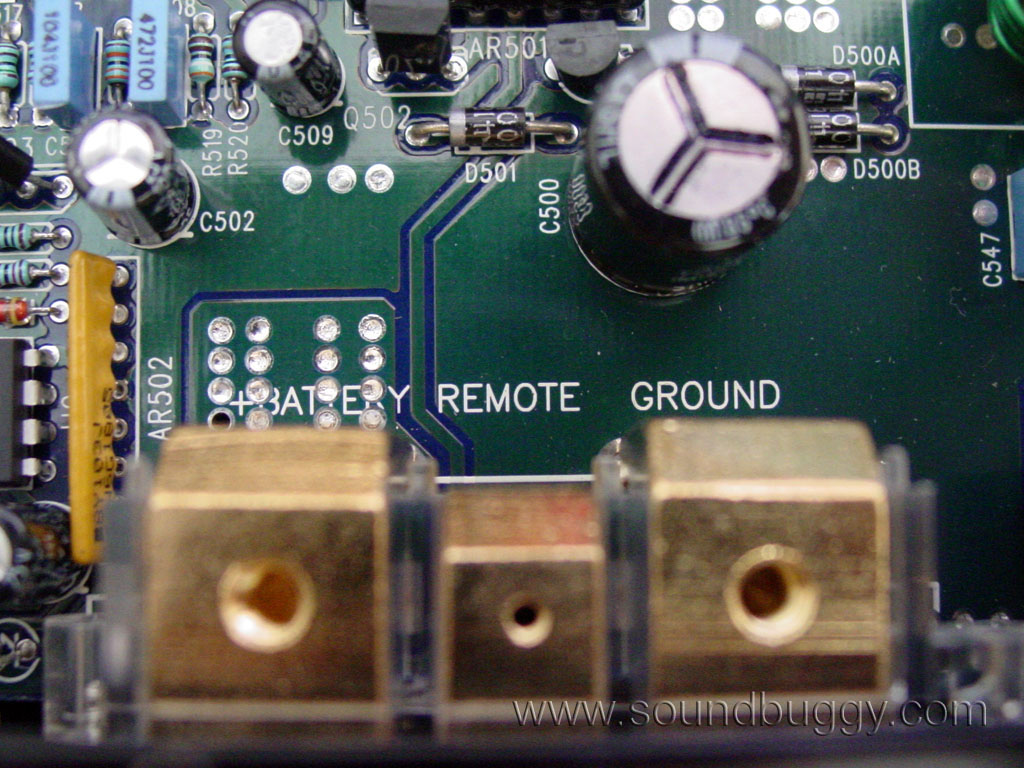
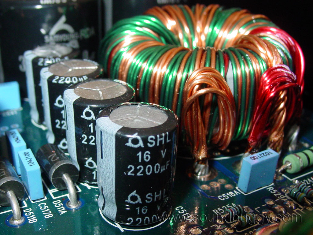
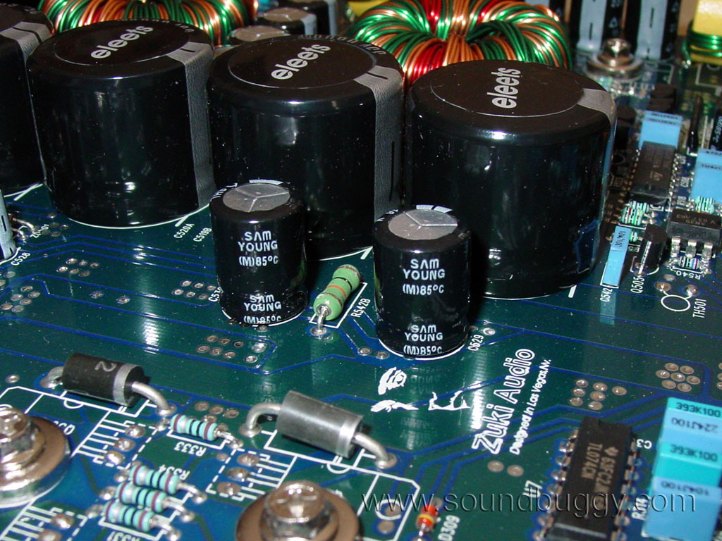
The power supply of the amp is well built. Starting with some very solid terminals, which are also bolted to the amps heatsink, current makes its way to eight storage capacitors, after traveling through input nulling inductors. The storage capacitors are 2,200uF and are in two groups of four.
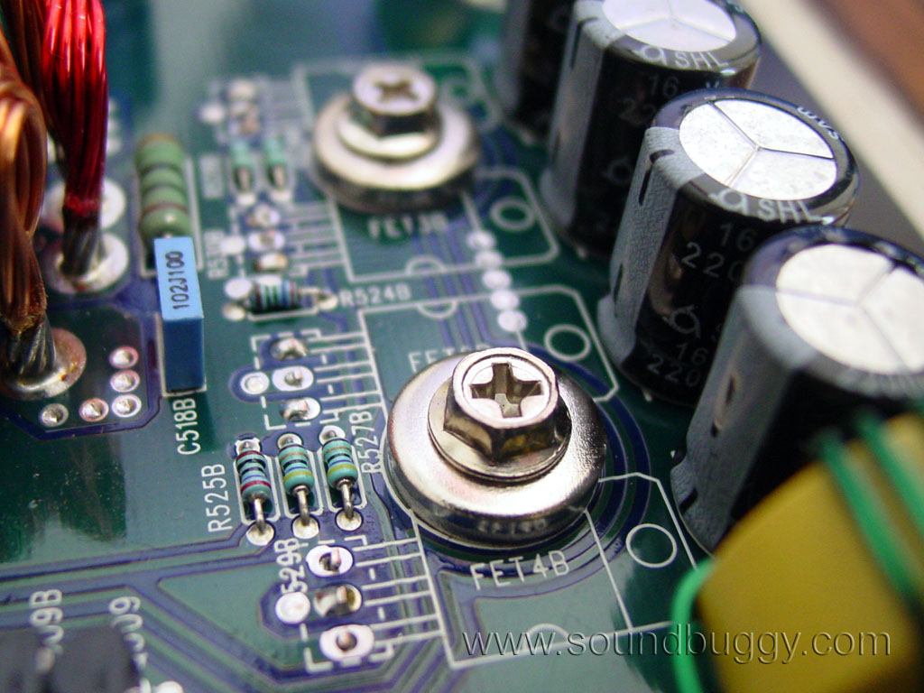
This amp has dual power supplies. One for channels 1 and 2, and a second for channels 3 and 4. This is mostly a guess. One could be for right, and one for left but I highly doubt it. Four TO-220 sided transistors are used for each power supply. I assume these are MOSFETs, but would not know without removing them from the board to find out.
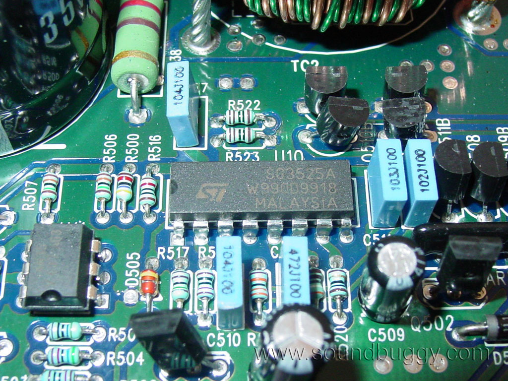
A SG3525 PWM controller is used for power supply switching. This is common in Phoenix Gold amplifiers and many others. I personally am a big fan of it for its ability to directly drive power supply MOSFETs without needing additional driver transistors or other active components.
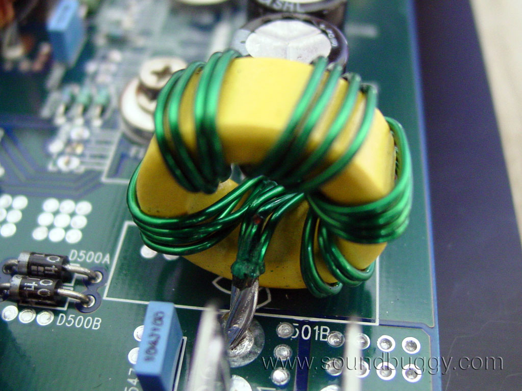
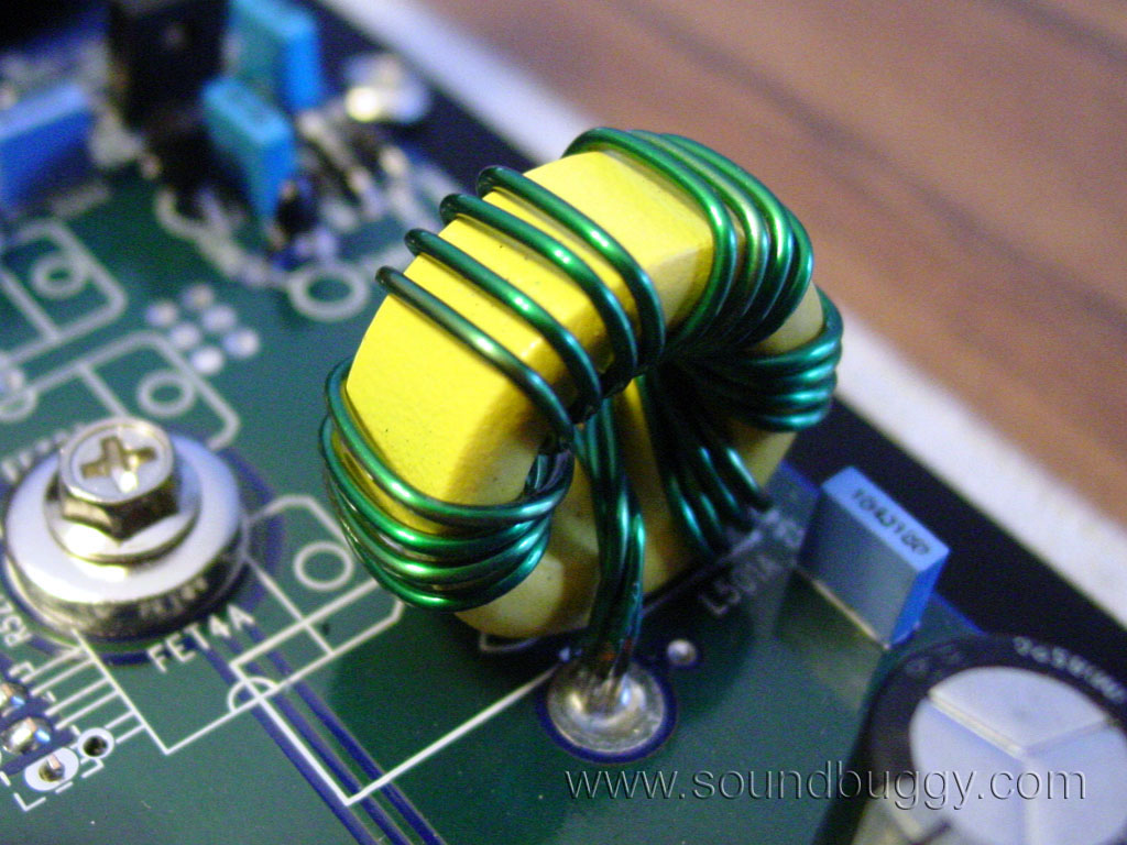
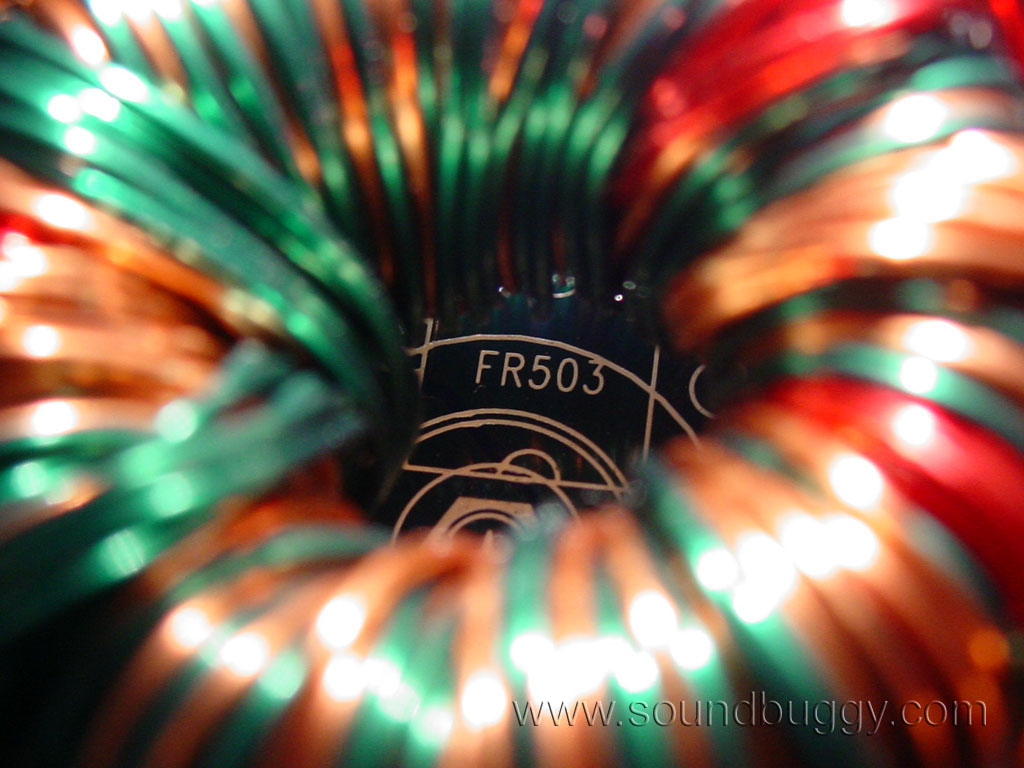
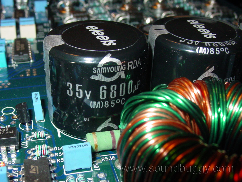
Because of the dual power supplies, two transformers are used. They appear to be high quality and are tightly wound with many smaller wires. This is often only found on higher end amps, with cheaper amps opting for smaller numbers of larger gauge wires usually wound in a disorganized way.
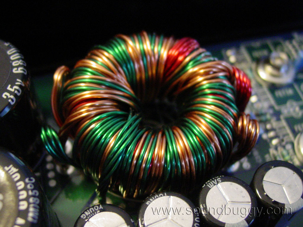
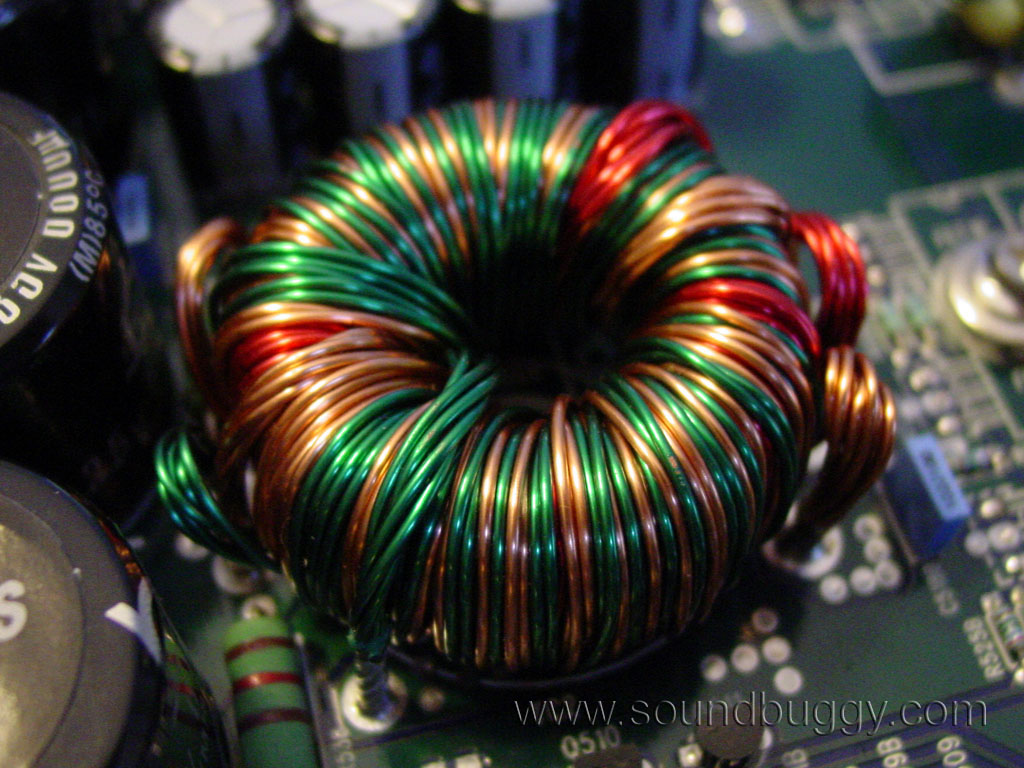
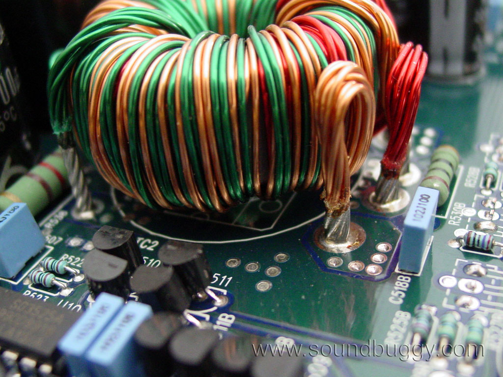
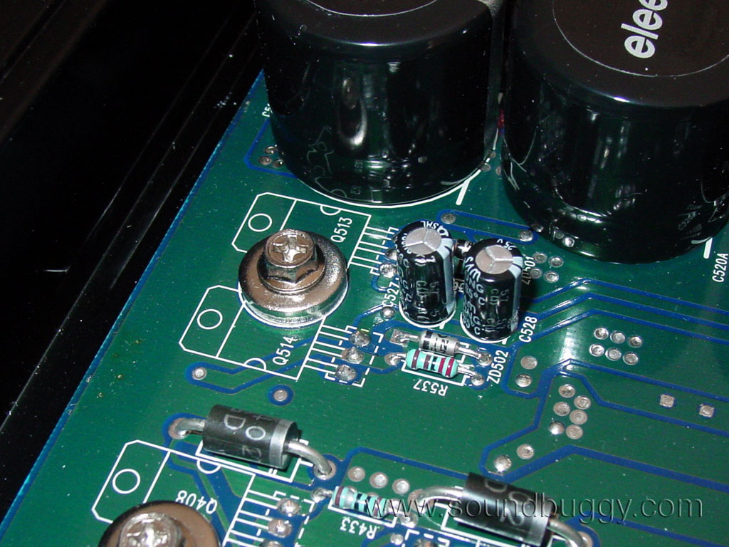
One of the most impressive features I found on this amp is a very simple one. The power supply rectification diodes are located under the transformers. In any other amp design, this is just wasted space. Well, Zuki placed them here, and not only is there the bonus of using up the wasted space, but there is also much shorter paths for current to flow from the transformers. This could add up to greater current handling and better reliability. It actually took me awhile studying the amps design before I even found where these diodes were.
Once rectified, current is stored in four 6,800uF rail capacitors rated at 35V. The presence of 35V caps is yet another tidbit pointing towards far greater output than just 5W x 4.
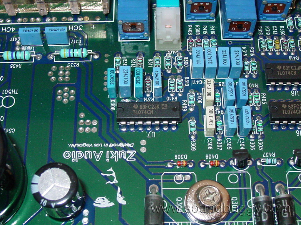
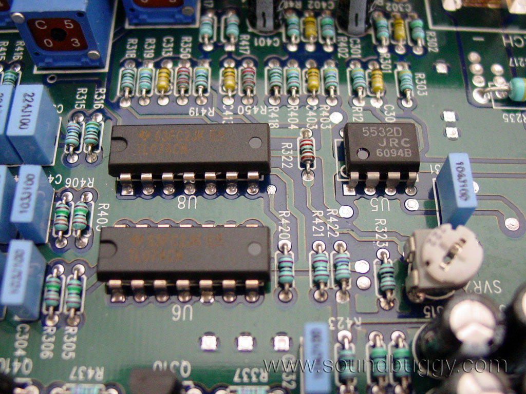
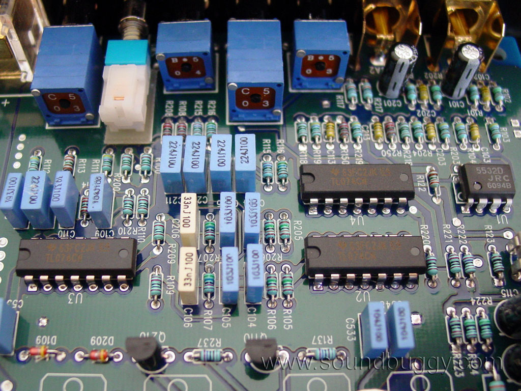
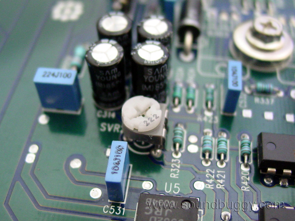
I found what I guess to be two voltage regulators used for the positive and negative voltage supplies required by the op-amps in the preamp section of the amp. I also found two larger caps out in space which I am guessing are for the op-amp supplies.
The preamp section consists of several op-amps and the required controls. It appears electrolytic caps are used for DC blocking purposes on the inputs. The op-amps are not your typical eight pin style, so there will be no DIY Burr Brown mods for this amp, at least not easily.
The output section of this amp is impressive. Eight TO-220 sized transistors are used for each channel. I do not know if they are MOSFETs or BJTs, and cannot tell without further disassembly of the amplifier.
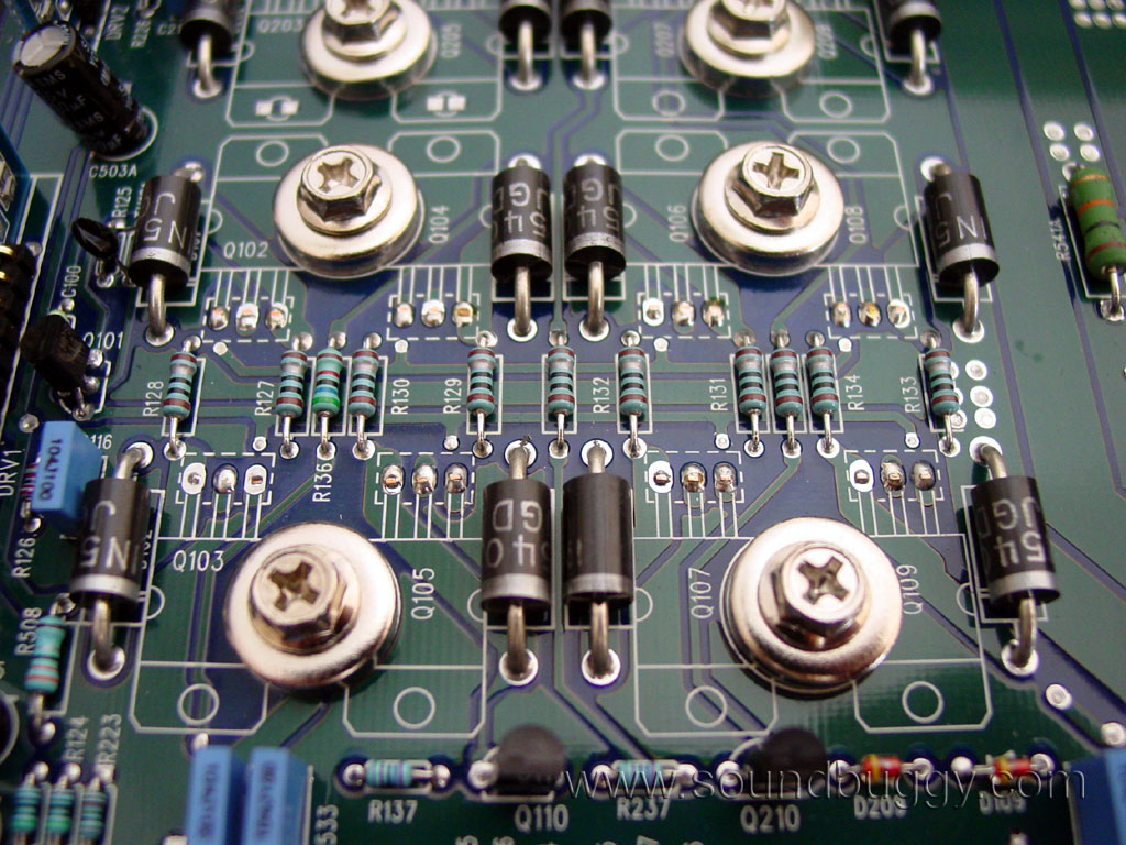
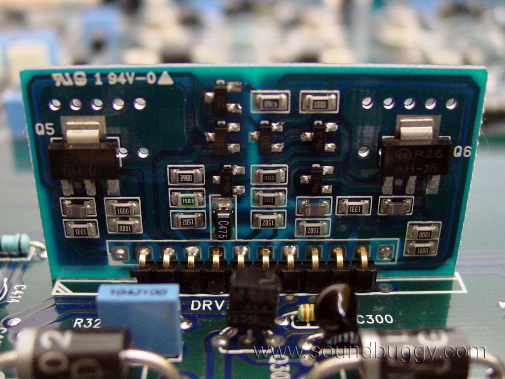
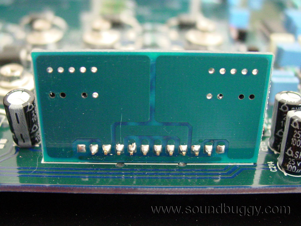
There are small daughter boards used for the redundant stages of the amp. I am guessing voltage gain, and maybe one stage of current gain if indeed the amp uses BJTs for outputs. The whole amp is thru-hole except for these surface mount boards.
The real mystery for me is the lack of bias controls, and the lack of output emitter resistors. I have seen amps before with no bias controls, and instead they used a self bias circuit. I have never seen an amp without emitter resistors. There are large diodes instead, one for each output device.
Class B amps can be built with sufficient feedback to eliminate crossover distortion, and therefore have the sonic qualities of a Class AB amp. Class B amps do not need bias controls. It is possible this is a Class B high feedback design. One other possibility is the diodes are somehow being used to force the amp into Class AB operation. This would likely be through their 0.7V drop which would match to the 0.7V drop across the output transistors. I have seen diodes and emitter resistors in SoundStream Class A amps, but I have yet to see the complete lack of emitter resistors. This topic is also being discussed online in various forums. Some people have noted that Genesis has used this design in the past.
There are two potentiometers inside the amp, and my very best guess as to their use is for gain tweaking to match the left and right channels at the factory. Since this amp uses a single gain control for each pair of channels, a potentiometer could be used internally to match the channels very closely (later in the review I find the channels are not that well matched, so my idea of the use for these is likely wrong).
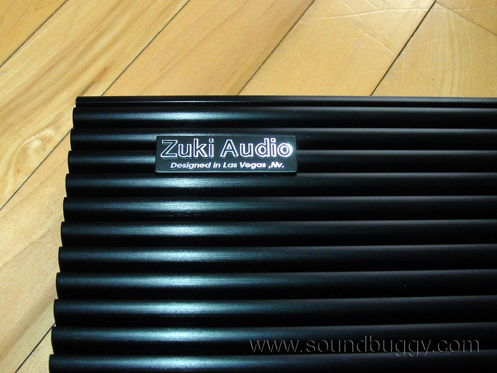
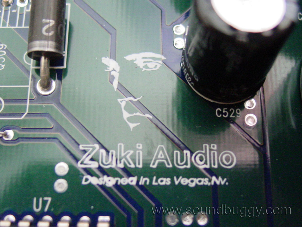
The Zuki logo is printed on the board in two locations.
All of the small capacitors on the amp are the plastic cased style similar to WIMA capacitors. I personally prefer this over the typical dipped style caps as they are more organized and don't get bent into each other.
My best guess is this amp is manufactured in the same Korean factory as Phoenix Gold Xenon amps were. There are a lot of similar parts and similar high level of quality. This amp is very well built and it is obvious a lot of consideration has gone into its design.
Performance:
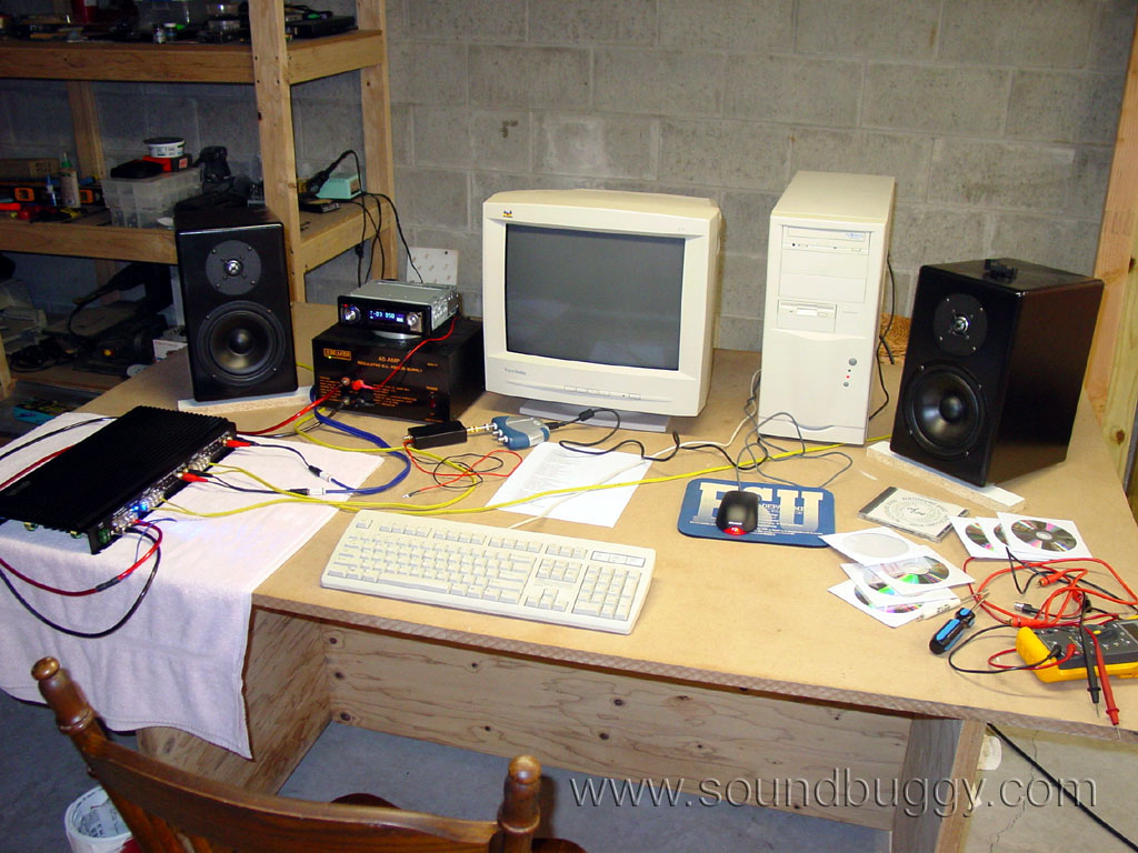
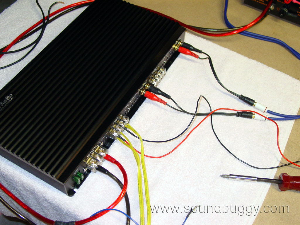
The big discussions on these Zuki amps tend to revolve around their very minimal power ratings. At 5W x 4, one wonders how loud they could possibly be or even how good they could sound. I for one am a skeptic, as I have found time and time again with my own personal audio experiences, the more power you throw at the situation, the more sound quality improves. Below are some photos of my thrown together test bench, so you can get an idea of what I had to work with to generate my findings.
The very first test I performed on this amplifier was to measure its unclipped output voltage. In the past, when I have performed this test, it has stirred up quite a bit of controversy. Some feel it is a useless test, as with most any amp on the market, its output level will fall once you place a load on it. Well even though this is completely true, few people listen to test tones alone. If you listen to music, it is of worth to know the maximum output your amplifier will provide prior to clipping.
Most amplifiers these days are built with an unintelligent consumer in mind. They know the consumer will crank the gains up to the max and do everything else in their power to destroy the amplifier in their quest to be the loudest moron on the block. With this in mind, manufacturers will build their amps to produce rated power into extreme loads, and with very high levels of clipping to the point of being square waves.
Zuki Audio as I will explore below takes an entirely different approach.
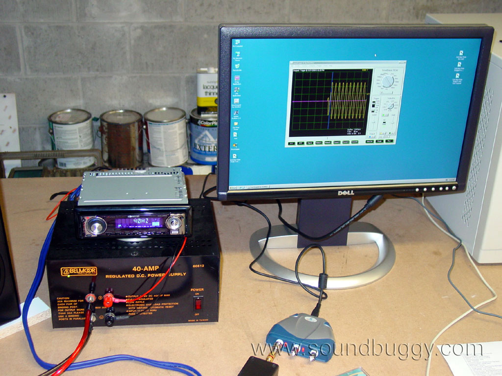
I played a 1kHz sine wave signal into the amp and adjusted the gains for the maximum unclipped output. I used my "stingray" USB oscilloscope to find this. For those interested, here is link to a review of this o-scope which I wrote (link). Here is a screenshot.
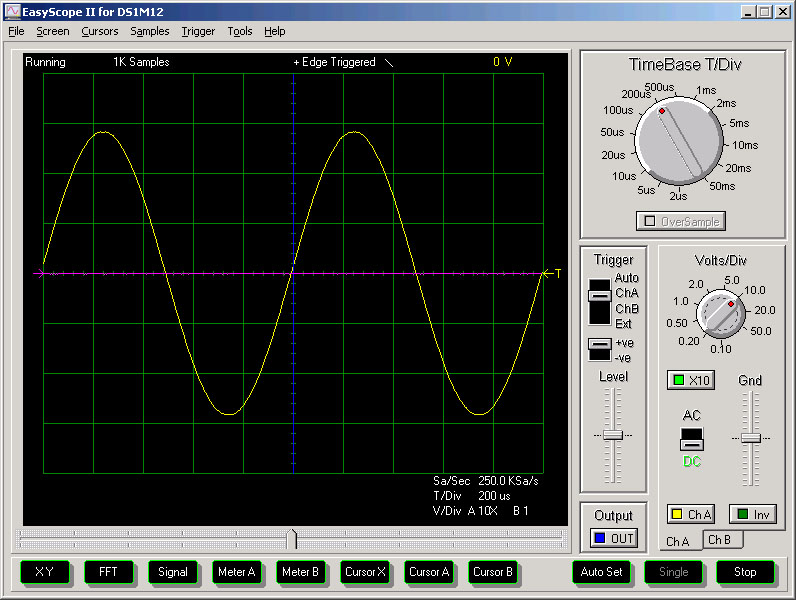
I used my Fluke True RMS DMM to measure the output voltage at 28V RMS prior to clipping. I won't go into great detail here, but I could not use my stingray to measure the voltages, as I had to create a 10-1 voltage divider on its input, and the circuit was not exactly 10-1, which shifted the measurements from the o-scope. I plan to purchase a 10-1 differential probe when I come up with some spare disposable income. For purposes here, the o-scope was used to visualize the signal and detect clipping, the DMM was used to measure signals.
Now, if you do a bit of math, 28V RMS works out to 196W a channel into a 4 ohm load. This is incredibly impressive compared to the rated 5W output. If you look back to some of my photos of the internals on this amp, you will notice I found two potentiometers on the board which I assumed were used to independently adjust the outputs of each channel to match. This is especially useful since the amp has only a single gain control for each pair of outputs. For the purist who wants things just right, they would need to externally use a processor which has separate left and right gain controls, or the Zuki amp would have to have been internal gain matched from the factory. Well, when I hit 28V RMS on one channel, I checked the second closest channel and found it to be only 26.41V RMS, which would be only 174W. Although you likely will not hear a 22W difference when listening to these high of levels, it still is slightly disturbing to me these channels are not closer, especially considering the audiophile market position of this amp. With channel 3 set at 28V, channel 4 output 25.55V.
Now, with this amp having a pair of 30A fuses for protection, and being quite small physically, it is hard to believe it is a 200W x 4 amplifier. Some additional testing would be necessary. Since I have only a 40A power supply, and since I really could care less what this amp does playing test tones into harsh loads, I felt I could take a different direction with my testing and get some real world data. To do this I tried to create a dynamic test.
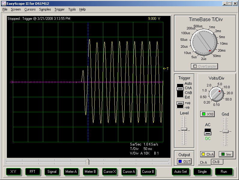
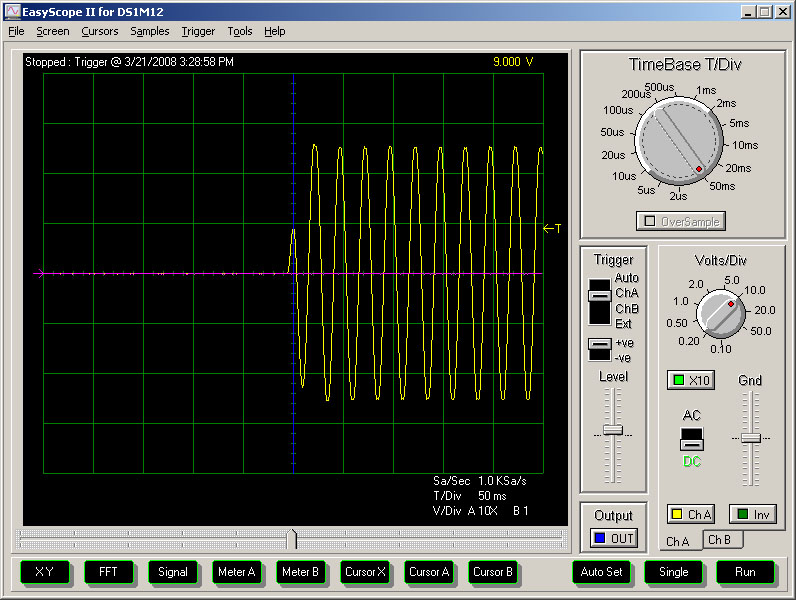
I first made a CD with two tracks. Track one was a 30 second long 40Hz tone recorded at 0db or digital zero. This track would be used to set the levels on the amp without a load. Track two was a 10 second digital silence, followed by a 40Hz tone which played to a duration of only 0.5 second. I used the first track to adjust the amp for no clipping and about 28V output. Using the triggering ability of my o-scope, I set it to capture the pulse of the amps output as soon as the input changed from silence to the 40Hz tone. Here is the no load signal...
Next I took the largest woofer I had near me and hooked it up to the amp. The woofer had dual 4 ohm coils so I put one coil on channels 1 and 2 bridged, and the other coil on channels 3 and 4 bridged. I then performed the exact same test.
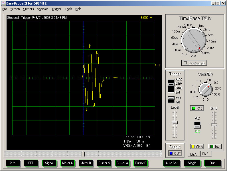
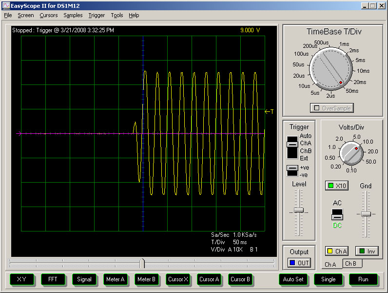
Now, if you look at the no load image, and this one of the woofer load, you will see the rapid decay in output. This was a result of two things. One, the amp went into protection and killed its output, two my supply exceeded its capacity and choked. It choked hard enough my head unit also connected to it lost sufficient voltage and shut off. Take a closer look at this data...
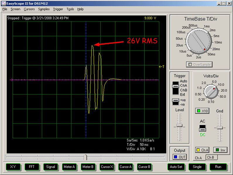
Keep in mind, the voltage you see on the graduations on the o-scope is not correct, as my 10-1 divider is not accurate. The voltage measured by DMM was 26V RMS at the spike you see. If you do the math, this is 169W RMS into 4 ohms, but then taking into account this amp had two bridged 4 ohm loads on it, this is a 1352W spike! This spike represents the combined efforts of the amps power supply, an internal capacitance for a split second (1-40th of a second to be exact).
Since my test resulted in the amp and my supply shutting down, I tried again using an easier load. I placed a single coil of the woofer on the single channel I was testing (channel 1), and performed the same test again...
This time the amp played just fine, and if you do a comparison between the no load test and the loaded test you will see the loaded output is 26V without and ramp off. I then took the second coil of my woofer and put it on channel 2 to add a bigger demand on the amp.
Again, 26V RMS output with no ramp off.
Now, my results are by no means the final word, but I am 100% confident this amp will do 175W RMS by 4 all day long playing music into component speakers at 4 ohms. My justification for this is the fact the amp has dual power supplies, one for each channel pair, so in a car there would be more current available to feed channels 3 and 4 with 4 ohm loads, and that driving a woofer at 40Hz signals is going to be far more demanding than driving component speakers.
I could go on all day testing this amp in different ways, but I also wanted to just take some time and listen to it. For listening, I bridged channels 1 and 2 into my left speaker, and channels 3 and 4 into my right speaker. The speakers were my Seas Embla DIY home speakers which are 8 ohms. This would put a 4 ohm load on each of the 4 channels in the amp. Prior to connecting the speakers I gain matched the right and left bridged outputs for 50V (25V a channel) each.
All I can say is WOW. This amp sounds great and there is no way I could tolerate playing it at the maximum output. For one thing my speakers would likely have died. I listened to a lot of dynamic music and noticed no drop in input voltage to the amp which is a good sign the internal capacitance is being put to use to smooth out the flow of current from the power supply when the amp demands more.
To verify the crossover works as intended and that the amplifier has no abnormal response characteristics which attribute to its excellent sound, I ran some response curves using my LMS. These curves were taken with no load present.
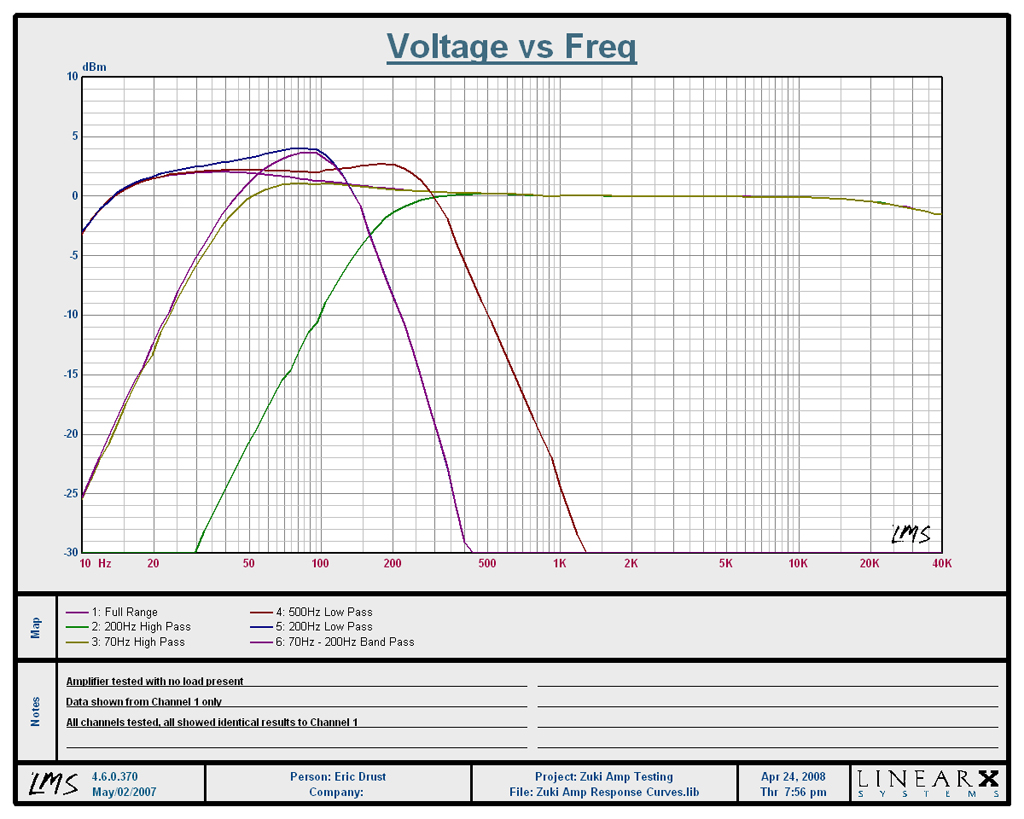
This amp is clearly not the flattest amp in the world. I doubt the 2db rise really adds much to the response, but it is not as flat as I would have liked to have seen. Based on the location of the rise, I am confident this is due to the non defeatable bass boost. Even in its minimum state it seems to be adding a bit to the signal. Notice the owner has the ability to create a band pass filter using the two overlapping crossovers. This could be very handy in certain situations.
One additional bonus of this amp is lack of heat. I played hard on it for several hours (it sounded so good I was drawn to listening to it for so long), and the amp was just slightly warm.
Final thoughts:
Would I buy this amp? YES. As a matter of fact, I am considering buying this amp from the group who got together to buy it for me to review. I really like it that much. There are still plenty of other amps out there I like very much, but they are not as functional as this amp is. To get this kind of power level you typically have to get an amp which is at least twice as physically big, and often with a bunch of added cosmetic junk or LEDs all over it.
Here is a snapshot of my findings about this amp.
1) It has very high output when playing dynamic signals such as music, almost 200W a channel into 4 ohms.
2) It does have a protection system of some sort which shut it down in my most extreme test.
3) It generates very little heat, especially considering its high output power.
4) It is very small for its size and power output.
5) This amp has no bias controls or output emitter resistors.
6) This amp is not a clone of a SoundStream or Genesis amp, and is unique, despite sharing some design features.
7) Purely my opinion, but I think it sounded great.
This amp does what it was designed to do, it plays music, and plays it well. It is not an SPL amp and in that case could very well burn up. It has so much headroom, no other amp I have ever dealt with has come even close. Feature wise it is a bit lacking, missing audiophile touches such as a fully defeatable crossover, and no onboard bass boost. Since each channel is not identical output, I would have preferred to see the bass boost control be replaced with another gain control, so there were separate gain controls for all channels.
To my knowledge Zuki Audio is new to the game of making amps. This amp really raises the bar for practical performance, and if they continue down this path, they will be a force to be reckoned with. Based on the market direction in the past several years, I feel Zuki amps are a return to the good old days of car audio with amps built to perform connected to speakers, not connected to your eyes on the shelf of your local Best Buy.