Via Repair Tutorial
Removing rail capacitors can be quite challenging. For this reason I highly recommend against replacing them, unless they are obviously damaged. If they look good, they most likely are good, as these items almost never rail.
Most people end up pulling the via out when they remove the rail capacitor. When they put the new cap in its place, it will conduct on the bottom of the socket, but not the top. In the case of many amplifiers, the board design requires current to flow from the top to the bottom or the other way. If a channel of the amplifier does not get one side of the rail voltage, catastrophic damage can occur. The unbalanced nature of the rail will put excess voltage across many parts which are not rated for it. These parts will heat up and fail.
If the amp you are working on had rail fuses, I highly suggest removing those fuses for the initial power up of the amp after replacing the rail caps. You can quickly measure the voltage at the fuse holders to verify if you got the replacement right.
In the event you do damage the vias, this is one of many methods you can use to repair them...
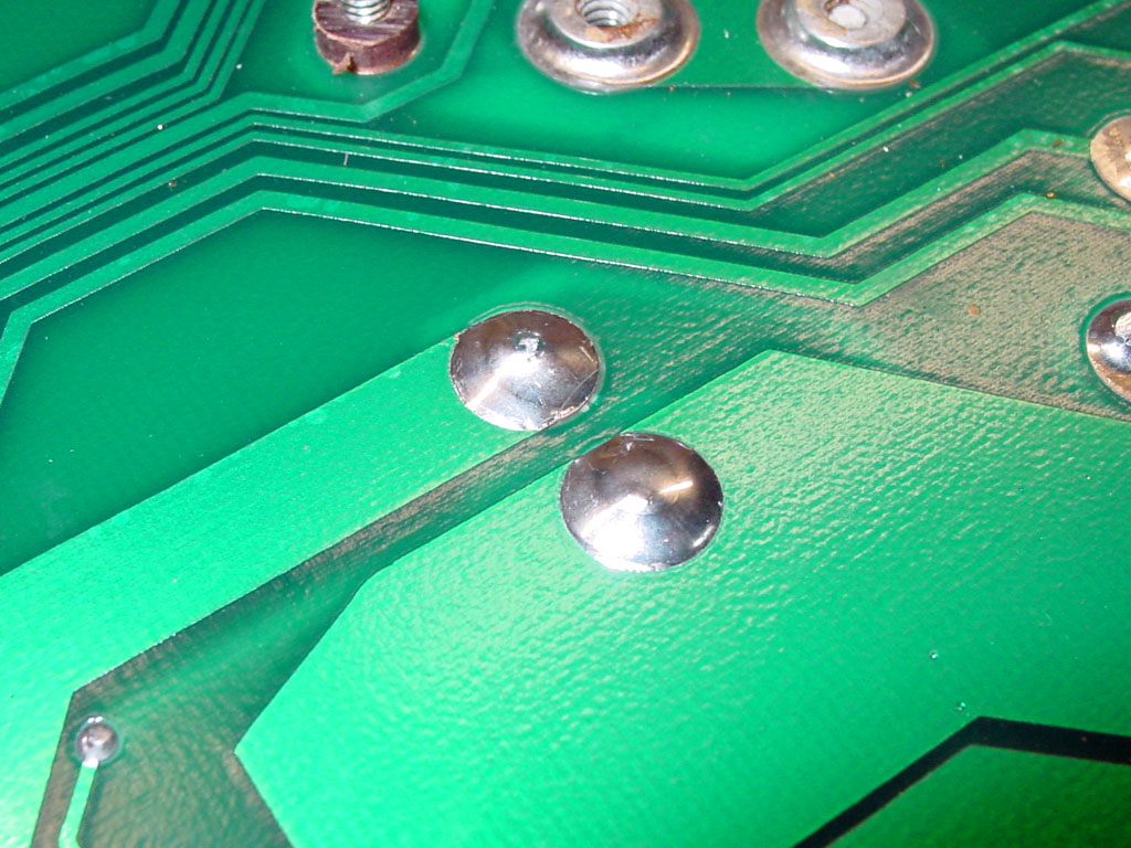
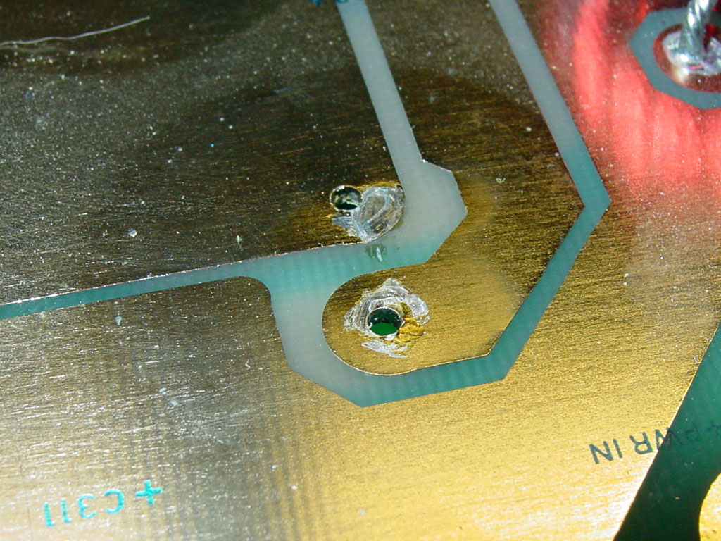
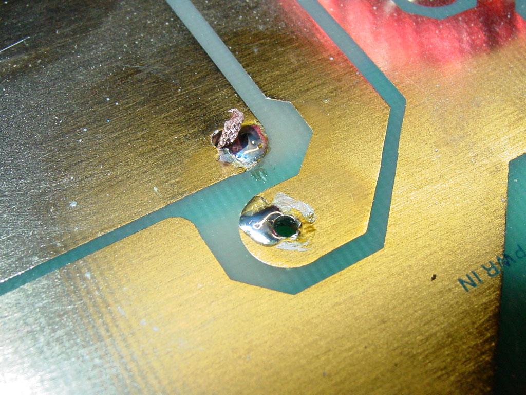
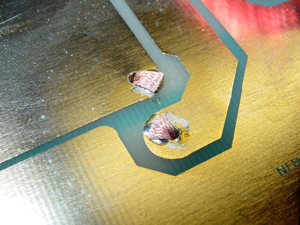
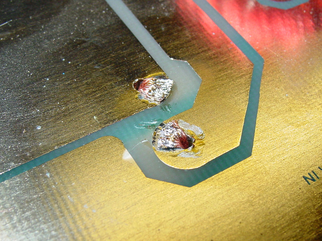
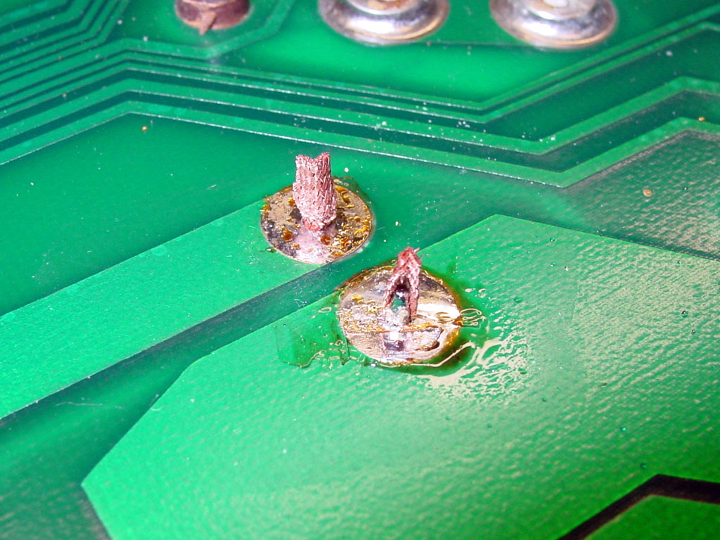
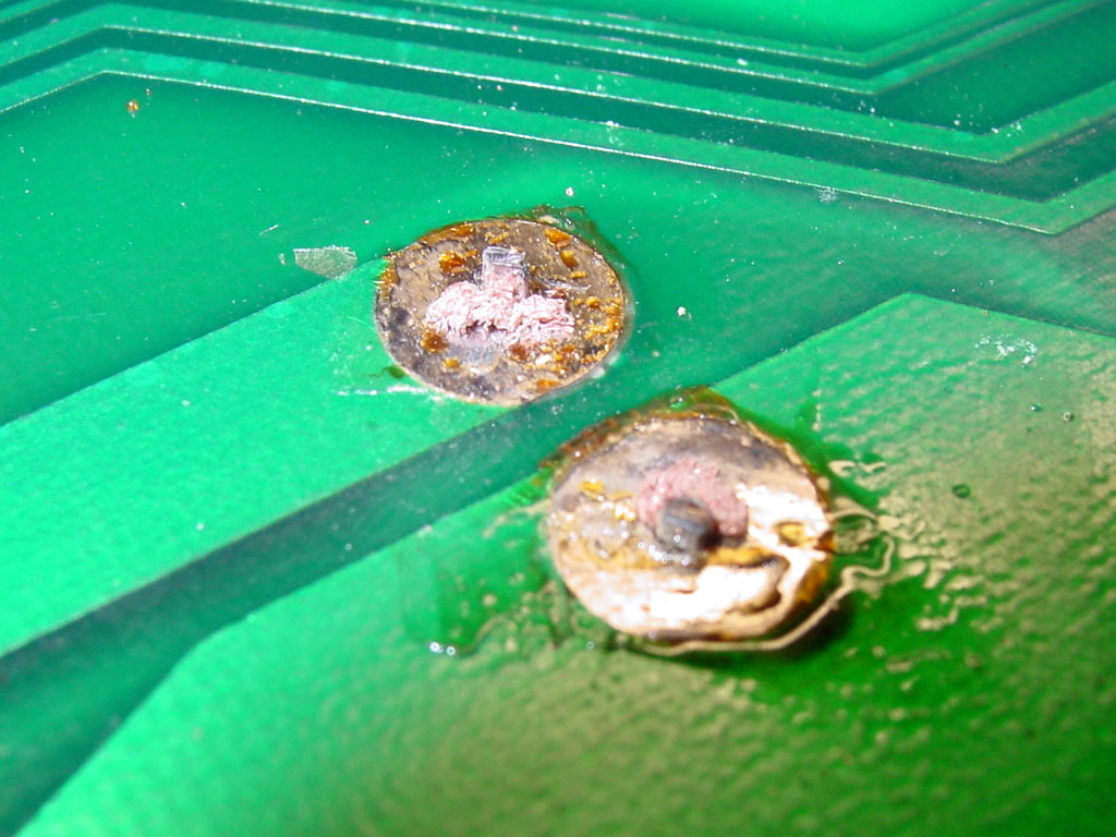
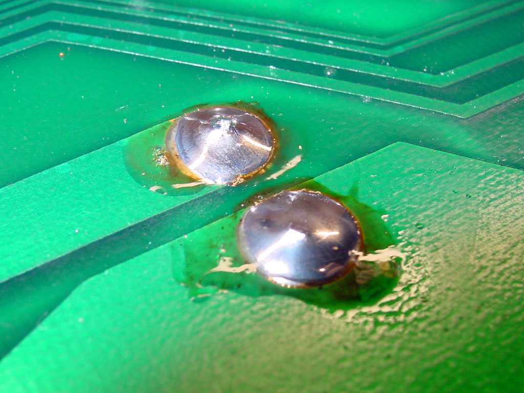
Here the damaged vias are shown. Click the images for a 1024x768 detailed photo.
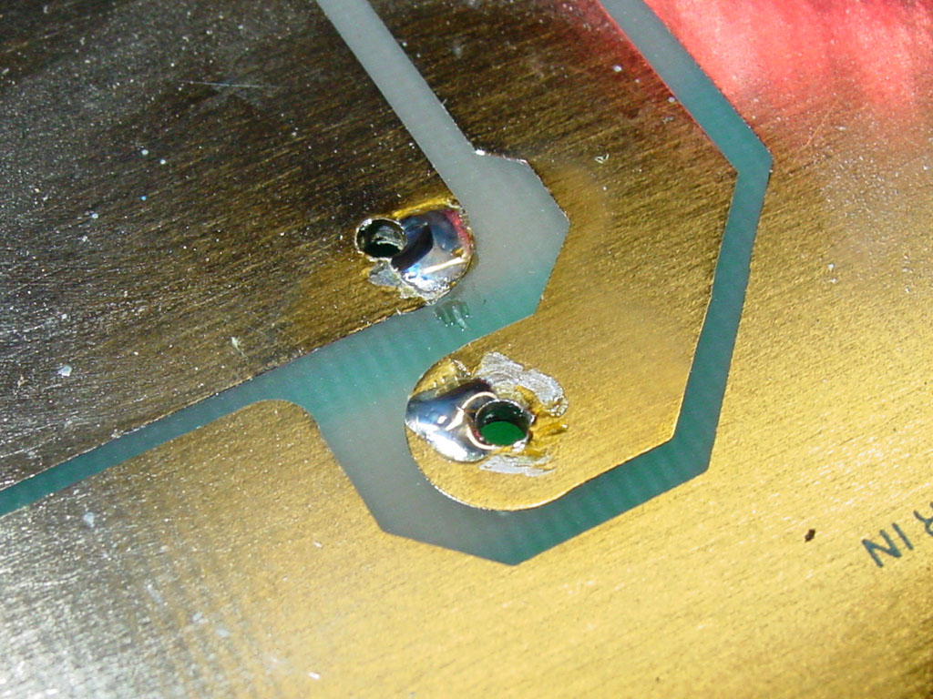
First place small globs of solder on the sides of the holes as shown.
The snap-in cap leads are flat and you should place the solder as shown so it does not interfere with the pins themselves.
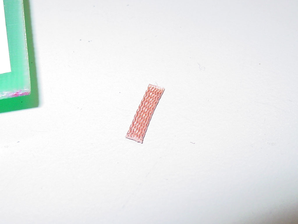
Cut a short piece of 1/8" solder wick.
Place have of it in a set of needle nose pliers.
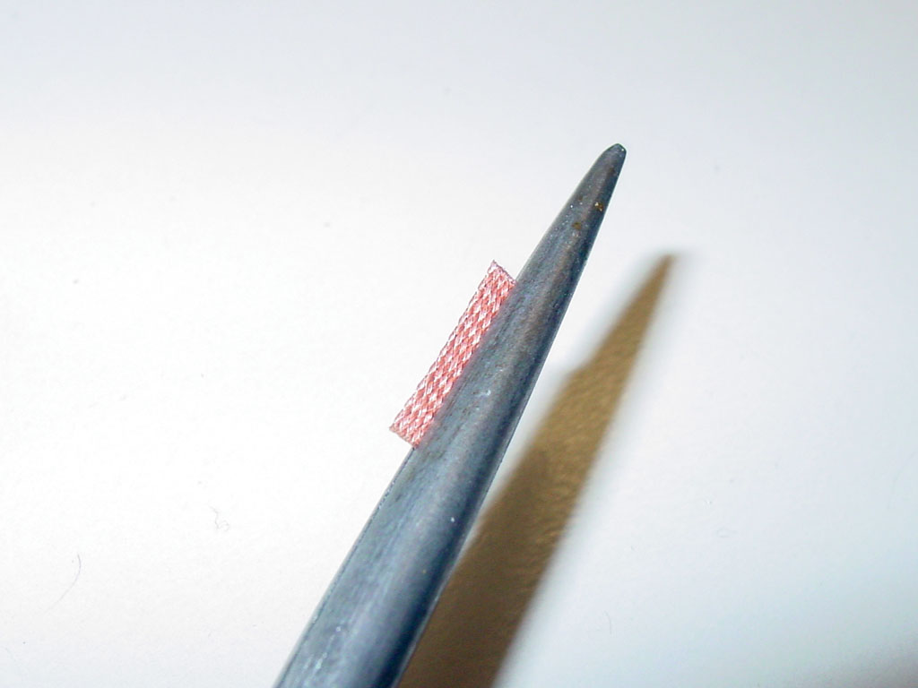
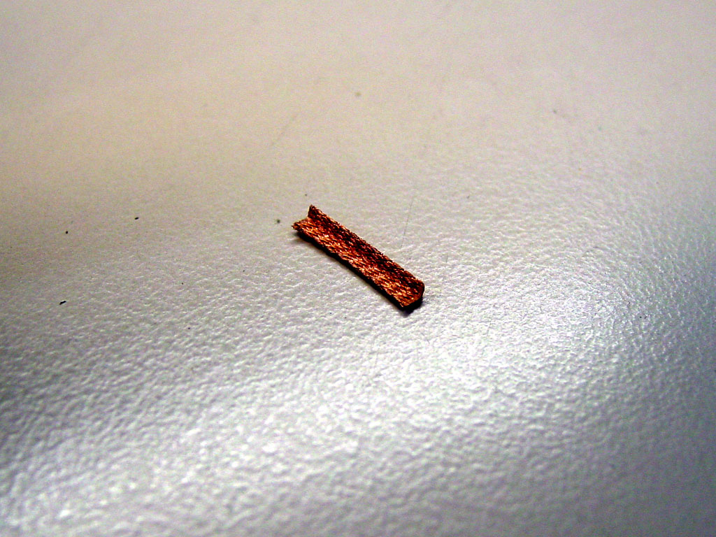
Bend the wick over.
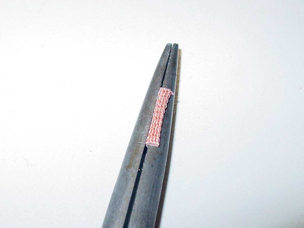
You get this.
Insert into hole with the direction shown.
Bend the top portion over as shown.
Carefully solder the wick to the globs by pressing the iron down into them.
Be sure to not let the solder flow down the wick into the via.
Insert the cap and flip the board over.
Trim the excess.
Solder.
Clean off excess flux and your done.